Things You'll Need
Lug wrench
Jack
Socket wrench
Metric socket set
Ball joint remover
Bearing remover
Bearing press
Plastic hammer
Torque wrench
breaker bar
Instructions
1 Loosen the lug nuts. Raise the vehicle with a jack and remove the wheel. The jack point is a thicker, reinforced edge at the bottom of the body panel directly behind the
front wheel.
2 Remove the bolts from the brake caliper and hang the caliper from a length of scrap wire. Do not allow it to hang from the brake line.
3 Remove the disc by unscrewing the retaining screws and driving a pair of 8mm bolts through the disc, pushing it away from the hub.
4 Remove the anti lock brake sensor and wire bracket from the steering knuckle.
5 Remove the upper and lower ball joints.
6 Pull the steering knuckle outward. Disconnect the drive shaft joint with a plastic hammer to fully remove the knuckle.
7 Remove the circular clip that holds the bearing in place. Push the bearing out of the steering knuckle. Remove the inner race with a bearing remover tool.
8 Press the replacement bearing and track into the knuckle with a bearing press. Install the clip. Reinstall the steering knuckle, attach the wheel and lower the vehicle.
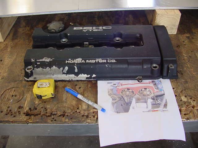
Tools needed: Valve Cover Drill 1/8 bit 3 1/2" hole saw& bit;-----Seems to be the perfect size Pilot bit holder thingy (don't know the exact name, sorry) Hammer Punch (or Phillips screw driver) A buddy (or a vice) Optional:A file to smooth down the edges.
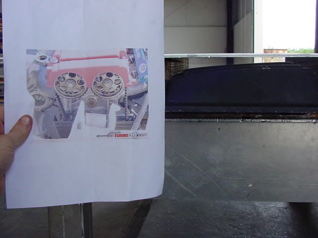
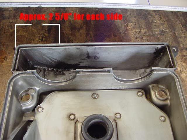
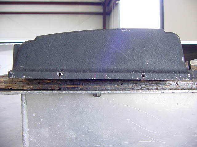
Step 1:Locate your valve cover, remove it and get your tools ready to modify your valve cover!!! What your starting out with. I used the pic as a size reference for the cam gears. Step 2:Measure to find the center of the cams. To the center of the lil slot, it's 2 5/8", approx. May be a 1/16th off or so.
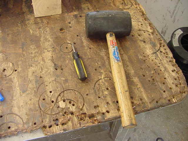
Step 3:Indent the valve cover where your going to drill, and drill a pilot hole. I made my indentions, using the hammer and a punch, about at the top of the lil ridge on the valve cover. Reference t3h pic plz.
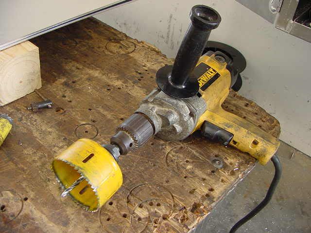
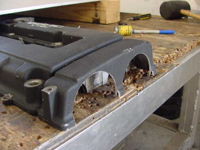
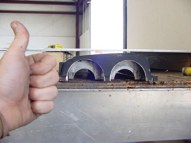
Step 4:Put the hole saw on the drill w/the pilot bit. Using a buddy or a vice (I used my good friend Dan) secure the valve cover so it won't move, muster up some courage and start cutting the valve cover. Maybe you'll end up with something like this. You know I gotta throw a thumbs up in there
Step 5:Optional:Using a file, file down the Sharpe edges till they are smooth. Don't want to possibly knick yourtimingbelt when you re-install your valve cover. This may keep you from possibly cutting yourself too Step 5(or Step 6 if optional step is used): Clean the valve cover. Don't want any bits of metal in your engine do you? I didn't think so. Clean it as best as you can.
DX,STD (DPFI) -> Si,HX (MPFI) wiring PARTS/TOOLS NEEDED Prices may vary depending on where you go) -SiECU(PM6for manual transmission)-----$75-$120 - Si Distributor--------------------------------$50-$120 - MPFI intake manifold - including throttle body, fuel rail, injectors----$70-$90 - Resistor Box(88-91 Si)------$20-$40 - Si wiring harness(needed for injector plugs, injector resistor box plug, and distributor plug)-----$0-$10 - Intake manifold gasket- (not needed but recommended)-----$15-$20 - Manifold Support Bracket ------$0-$10 - Si fuel line from filter to fuel rail-----$0-$5 - some extra wire ------$3-$7 - electrical tape or heat shrink(better)------$1-$10 - wire stripper/cutter------$5-$15 - soldering gun and solder(not needed but highly recommended)------$10-$18
Parts could cost anywhere between $230-$405 depending on what kinds of deals you can find and where you get them from, it may also be cheaper if you buy everything from one person all at once
It is much easier to use your existing DPFI harness and just add the extra 4 wires that will be needed. The Si harness will be much harder to use.
There are two major wiring changes that you'll have to do going from a DPFI system to an MPFI and a couple other minor things that need to be done too. The first one is the crank angle sensor wiring which is the easy part. The second one is the fuel injector wiring which is slightly more complicated. Also, you'll have to switch the two wires on the TPS because the TPS on the new intake works in the opposite direction. If you dont switch them, the ECU will think that the engine is at Wide open throttle when its actually at idle. I highly recommend soldering and heat shrinking any electrical connections you will be making because it is very possible for connectors to come loose from all the vibration and solder will hold up better in the long run. Also, the TPS and EACV plugs are too short and they'll have to be extended. You're also going to have to switch the manifold support bracket, since the bolt parrern from the support to manifold is different from DX to SI, although they still bolt up on the block the same. TO HOOK UP THE MULTI-POINT CRANK ANGLE SENSOR: - First, you'll have to go to the passengers foot well to where the ecu is located. - Pin B10 and B12 should both be empty. - You'll have to cut and move the wire that goes to pin C1(orange) over to pin B10, and move the wire from pinC2(white) over to pin B12. Don't get these two mixed up or else the ignition timing will be severly retarded. Leave enough wire at the ECU side of pin C1 and C2 for next step. - Now run wires from pins C1 and C2 into the engine compartment and label them. - There will be a connector on the new Si distributor with two unused pins. One of the wires will be blue/green stripe, and the other will be blue/yellow stripe. - The wire that is blue/green stripe will go to the wire from pin C1 on the ECU and the other wire that is blue/yellow stripe will go to the wire from pin C2.
SWITCHING THE WIRES AT THE TPS: This pretty much explains itself, just switch the two outside wires(green/white and yellow/white) around at the TPS and then you're done this step. I used the TPS connector off the Si harness, just so that I could just match up all the wires, since the wires are already reversed on it.
INJECTOR WIRING (In the car): First of all, while you're still in the passengers foot well, cut wires A3(yellow) and A7(red), although leave some wire on the ECU side for later use. Now run wires from pins A3 and A7 into the engine compartment and label them.
(Engine Compartment): - Mount the injector resistor box up on the drivers side shock tower. - Connect the yellow/black wires from the two DPFI injector harnesses and run it to the yellow/black wire on the injector resistor box. - Connect the yellow wire from the DX injector to the #1 injector (brown wire). - Connect the red wire from the DX injector and run it to the #3 injector (blue wire). - Connect the wire you labelled A3 to the #2 injector (red wire). - Connect the wire labelled A7 to the #4 injector (yellow wire). - Then, connect the 4 red/black wires coming from injector resistor box to each of the four injectors. Completed Wiring Diagram Distributor wiring completed
You should have three extra plugs left over after you are done the swap. two of them are the old DPFI injector plugs, and the other one is for the tandem valve for the DPFI system, which you do not use on the MPFI system, you can either just cut it off, or tuck it away somewhere.
OBD1 ECU PINOUT The # go up and down from left to right.(see)
Another thing make sure you have extra pin inputs since you will cutting the wire and not taking the complete wire out of its socket.
Firstoff, it generally helps to remove the hood from its support brackets. Pop the lifters and remove the four bolts.
Removeall of the associated pipework from the radiator (the system should be drained first) and remove the electrical connectors to the cylinder head and/or the wiring which will get in the way. Label the wires so you don't get mixed up when refitting everything.
Thecylinder head is a heavy piece of equipment, so sometimes it is easier to remove the intake manifold. Be careful that coolant will still be in the cylinder head and the manifold.
Instructions
1. Unplug all wires and hoses connected to the cylinder head and remove the head cover. You may need to remove the A/C fan to be able to clear it of the studs on the engine block.
2. Set the motor to "top dead center," or TDC. Remove the #1 cylinder's spark plug as well as the valve cover so you can observe the springs. Insert a screwdriver into the open spark plug hole, and rotate the motor by hand, counter-clockwise. When the #1 cylinder is on its intake stroke, watch the screwdriver. Turn the motor very slowly until the screwdriver reaches its highest point. Remove the screwdriver. Slide off the timing belt, and be sure you do not rotate the motor any further.
3. Remove the head bolts in order, and double check that no coolant lines are still connected. Lift the cylinder head out. It will be very heavy--this is where you'll likely need the help of another person. Remove the old head gasket.
4. Drain the oil from the cylinder head. Clean the pistons, valves, head bolt holes and all other parts with degreaser and a toothbrush. Wipe down with a paper towel when finished. Some people even run the same size taps in head-bolt holes to insure proper cleaning.
The biggest benefit to dealing with dis-assembly, lapping and reassembly one valve at a time is that you cannot accidentally install a valve in the wrong combustion chamber. In other words, each valve is lapped and installed in the same exact section of the head where it was originally installed. This is extremely important because no machining is being done to the heads to true things back up. Basically moving parts get where patterns over time and each valve and valve guide will where together as a matched set. Installing a valve from one chamber in to another chamber will result in unmatched where patterns and typically shorten the over all life of valve train and this is why it is so important to reinstall the valve in its original location.
Tools
New valve stem seals
Valve lapping compound (course/fine)
Valve spring compressor
Magnet
Suction cup
Napkins
Step 1 With the Head off the car you first need to remove the valves. Do this only one at a time as its best for the valve to go back in its original location. Take your valve spring compressor and place it as far at the bottom of the spring as possible and compress the spring. Then you need to take a magnet and remove the keepers. There's 2 on each valve you do. Step 2
Once the keepers are out put them somewhere you wont loose them! now you can lift the valve spring up and uncompress the spring. On the top of the spring is the retainer.
Now all you should see left is the valve stem seal. you need to get a gripping pliers and pull out the seal. You have to pull somewhat hard to get them out. once its out throw the old one away. If you see oil once the seal is off clean it up.
Step 3
You're now ready to get the valve lapping compound. You need to start with the coarse grit first. Put a little on your finger and go all the way around the valve as shown in the pic.
Step 4
Take the valve with the lapping compound on it and put it back in the head. Now take a small suction cup and put it on the valve and turn it side to side. this is lapping the valve. You will hear a grinding noise at first which means its working! Keep doing this until the noise quiets down. Then take out the valve and clean the lapping compound off it and also in the head. Then take your fine lapping compound and do the same thing with it until its quiet. Clean off the valve and inside the heads again.
Step 5
When your all done lapping and everything's clean put the valve back in and set the head down flat. The valve stem seals you got should have came with a small piece of straw. Put this on the top of the valve stem as shown
Step 6
Take the valve stem seal and push it down until it looks Flush on the cylinder head valve port. The seal wont go down all the way. This is normal. When you put your springs back on it will push the seal down automatically so dont even worry about it.
With the seal pushed down take the straw out. then take your valve spring and place the retainer on the top of it.
Step 7
Now compress the spring and place it on the valve stem seal. Get the 2 keepers and put them back in. You may want to get some white grease to put on the inside of the keepers to help them stick on. If your having trouble getting the keepers in place try compressing the spring more.
Once everything's in place take the spring compressor and lift it up until the retainer moves up to where the keepers are. Then uncompress the spring as shown.
Step 8
Your all done with this valve!!!! Repeat the same steps for the rest of the valves. Try to spend more time on the exhaust valves when your lapping because they need it more than the intake valves usually do.
After Lapping
1. With the guides straight, round, and snug,,,, in other words in good condition, not lose and worn out.
2. After you have accurately dressed your stone and ground the valves.
3. After you have done a careful valve job.
4. With the head upside down and the seats facing up, barely insert the valve in the guide.
5. With the valve held about 1.5 inches above the seat, drop the valve and it should bounce 2 or 3 times and ring like a church bell. That seat is concentric to the guide centerline.
6. If you drop the valve and it goes "thunk" and stays on the seat, then one side or the other is wedging against the seat. If your lightly raise the valve off the seat with your fingertip, from the stem end, you can feel some light resistance, that's further proof that you need to recut the seats.

.jpg)